Introduction
HM-10 is a BLE module for embedded system to get BLE wireless communication with BLE capable devices (e.g. iPhone and iPad). It is fully configurable by a rich and well documented AT command-set and allows transparent data communication via serial UART (default baudrate 9600bps).
The Bluetooth 4.0 HM-10 is basically a breakout board for cc2541, it broke out the LED pins, RX/TX and also adding the voltage regulator that regular 5v to 3.3 v.
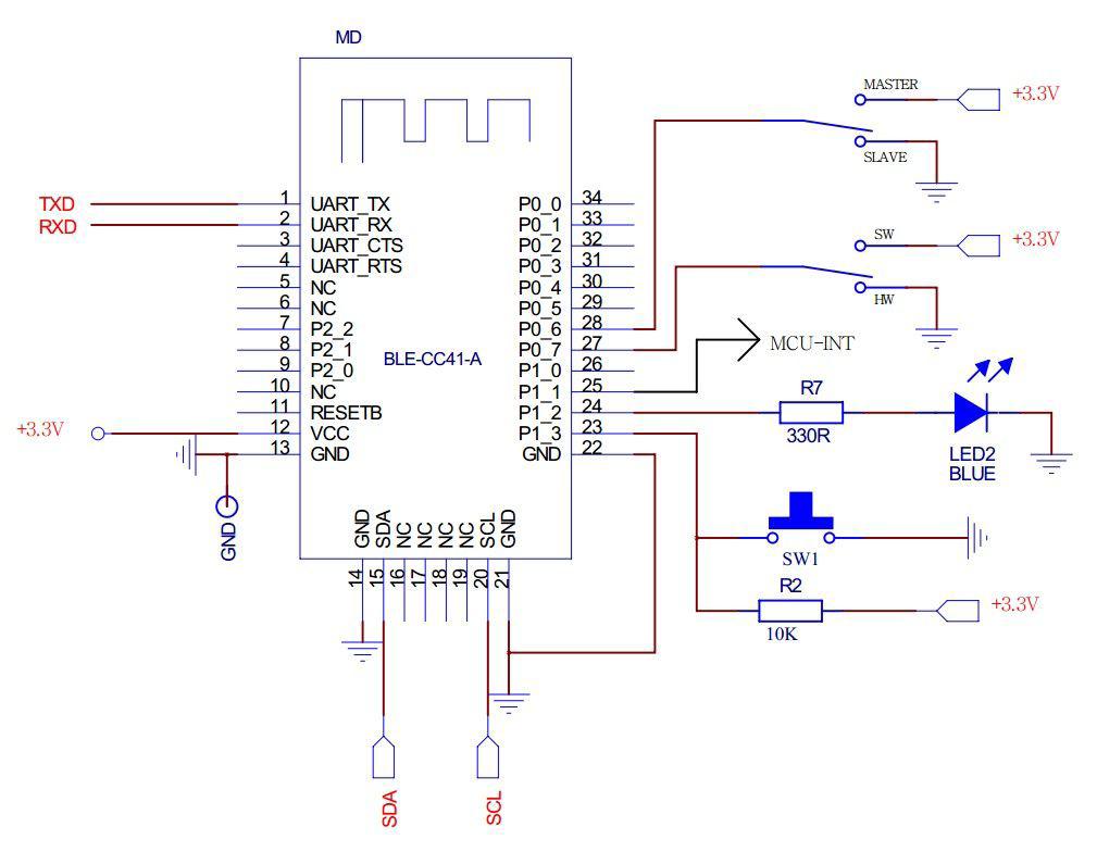
Bluetooth 4.0 HM-10 Master Slave Module
Setup with FTDI + Arduino Serial Monitor + AT Command
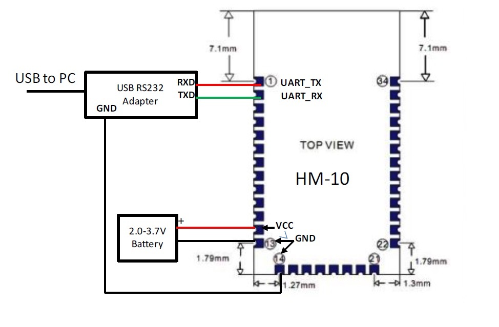
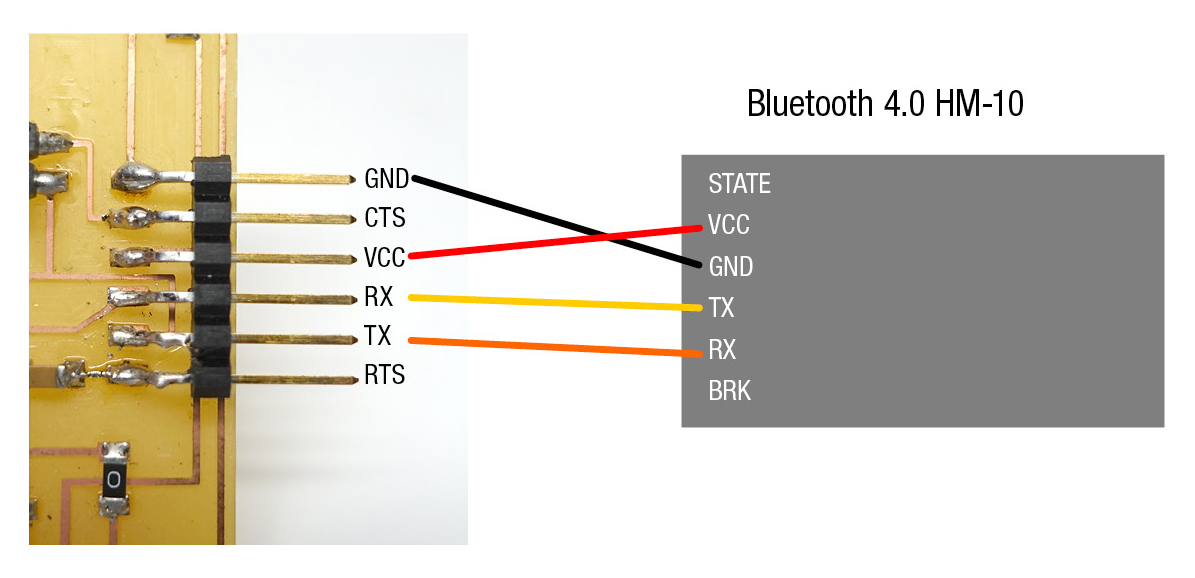
There are so many things that you can do with Bluetooth 4.0 HM-10, but first you need to setup with FTDI cable to understand what and how it’s doing.
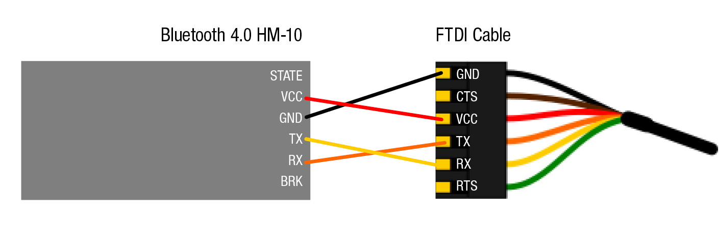
You will need a FTDI cable and 4 female to male wires to hook up to Bluetooth 4.0 HM-10 / BLE
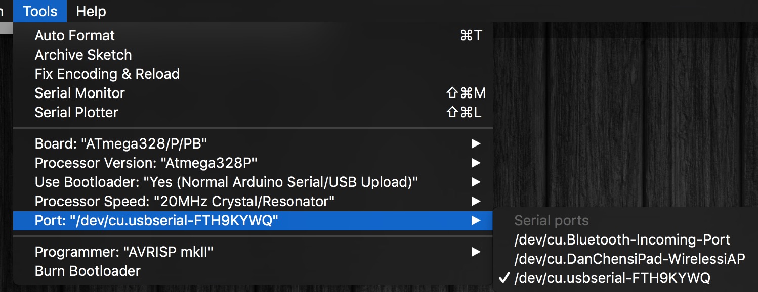
On your computer, open Arduino.
Make sure you select the correct usb serial port.
Open Serial Monitor and make sure the baud rate is 9600, this is the default baud rate.
Type in
AT+NAME? (NO SPACES IN AT COMMAND)
you should get OK+NAME:HMSoft
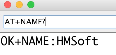
If it says nothing, check your connections.
Now we can talk to BLE with AT command and the rest is simple.
See more AT Commands at the very end of the post.
Sending & Receiving (Both Ways )
Setting the Master-Slave mode
With this method, you can turn the device on and have them talk to each other right away, without pairing, without initializing … it is wonderful. The data goes both ways.
First you will need to Query the native MAC address using AT Command AT+ADDR?
You will get something like this 20C38FF61DA1, each BLE has a unique MAC address.
Use AT+CON[param1] and AT+ROLE[param1] to pair to another device.
Example
BLE A has Mac Address 11C11FF11DA1
BLE B has Mac Address 22C22FF22DA2
Send AT+CON22C22FF22DA2 to BLE A
Send AT+CON11C11FF11DA1 to BLE B
(Send the B address to A, A address to B)
Send AT+ROLE[0] to BLE A
Send AT+ROLE[1] to BLE B
(Doesn’t matter which one)
Now it’s ready to use on you ATMEGA 328P, Arduino or Attiny.
The red light will stay solid after the connection has been made on both BLE. This should take less than a second.
Sending & Receiving on ATMEGA 328P / Arduino
It’s very easy to talk to ATMEGA 328P / Arduino with the BLE, you can just use the hardware serial. Software serial will work for Attiny 44.
You can put the sketch on either one and let one does sensing and one does sensing. The data can talk both ways! Just Serial.println(Whatever you want);
In this code, one of the ATMEGA 328P /Arduino board “analog reads” the potentiometer data and sends serial data via BLE. On the other end, the other ATMEGA 328P /Arduino receives the serial data to move the servo.
AT Commands & Configuration
1) Query the native MAC address
Send: AT+ADDR?
Send after a successful return: OK + LADD: MAC address (address for 12 string)
2) Query the baud rate
Send: AT+BAUD?
Send after a successful return: OK + Get: [para1]
Scope of para1:0 ~ 8. The parameters corresponding to: 0 represents 9600, 1, 2, 9600, 38400, on behalf of the representative representative of 57600, 115200, 5, 4800, 6, 7 represents 1200, 1200 2400. The default baud rate to 9600.
3) Set the baud rate
Send: AT+BAUD[para1]
Send after a successful return: OK + Set:[para1]
Example: send: AT + BAUD1, return: OK + Set: 2.The baud rate is set to 19200.
Note: after the switch to the 1200, module will no longer support the configurations of the AT command, and press the PIO0 under standby, module can restore the factory Settings.Do not recommend using the baud rate.After setting the baud rate, modules should be on electricity, anew set parameters can take effect.
4) from the device connected to the bluetooth address specified
Send: AT+CON[para1]
Send after a successful return: OK + CONN[para2]
Para2 range is: A, E, F
Example: from the bluetooth address is: 0017EA0943AE, sending the AT + CON0017EA0943AE, module returns: OK + CONNA or OK + + CONNF CONNE or OK.
5) removal equipment matching information
Send: AT+CLEAR
Send after a successful return: OK + CLEAR
Clear success had connected device address code information.
6) query module working mode
Send: AT+MODE?
Send after a successful return: OK + Get: [para]
Para: the range of 0 ~ 2. 0 represents passthrough mode, on behalf of the PIO acquisition + remote control + 1 passthrough, 2 representative passthrough + remote control mode.The default is 0.
7) set module working mode:
Send: AT+MODE[para1]
Send after a successful return: OK + Set: [para]
8) query device name
Send: AT+NAME?
Send after a successful return: OK + NAME [para1]
9) set the device name
Send: AT+NAME[para1]
Send after a successful return: OK + Set: [para1]
Example: Set the device name to Seeed, sending the AT + NAMESeeed, return OK + Set: Seeed AT this time, the name of the bluetooth module has been changed to Seeed. Note: after the instruction execution, required to electricity, set the parameters of the approval.
10) query matching password
Send: AT+PASS?
Send after a successful return: OK + PASS: [para1]
Para1 range is 000000 ~ 999999, the default is 000000.
11) pairing set password
Send: AT+PASS[para1]
Send after a successful return: OK + Set: [para1]
12) restore factory Settings
Send: AT+RENEW
Send after a successful return: OK + RENEW
Restore the default factory Settings module, the module Settings will be reset so, back to the factory with the status of the factory default, delay module 500 ms after the restart.If no need, please be careful.
13) module reset
Send: AT+RESET
Send after a successful return: OK + RESET
After the instruction execution module will delay 500 ms after the restart.
14) set the master-slave mode
Send: AT+ROLE[para1]
Send after a successful return: OK + Set: [para1]