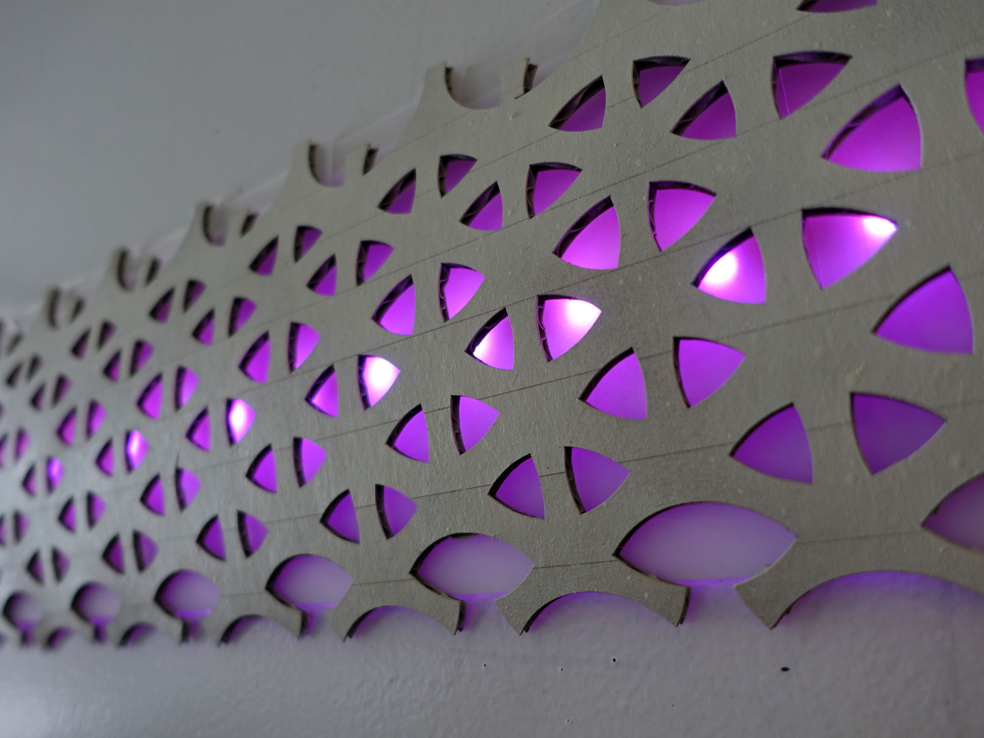
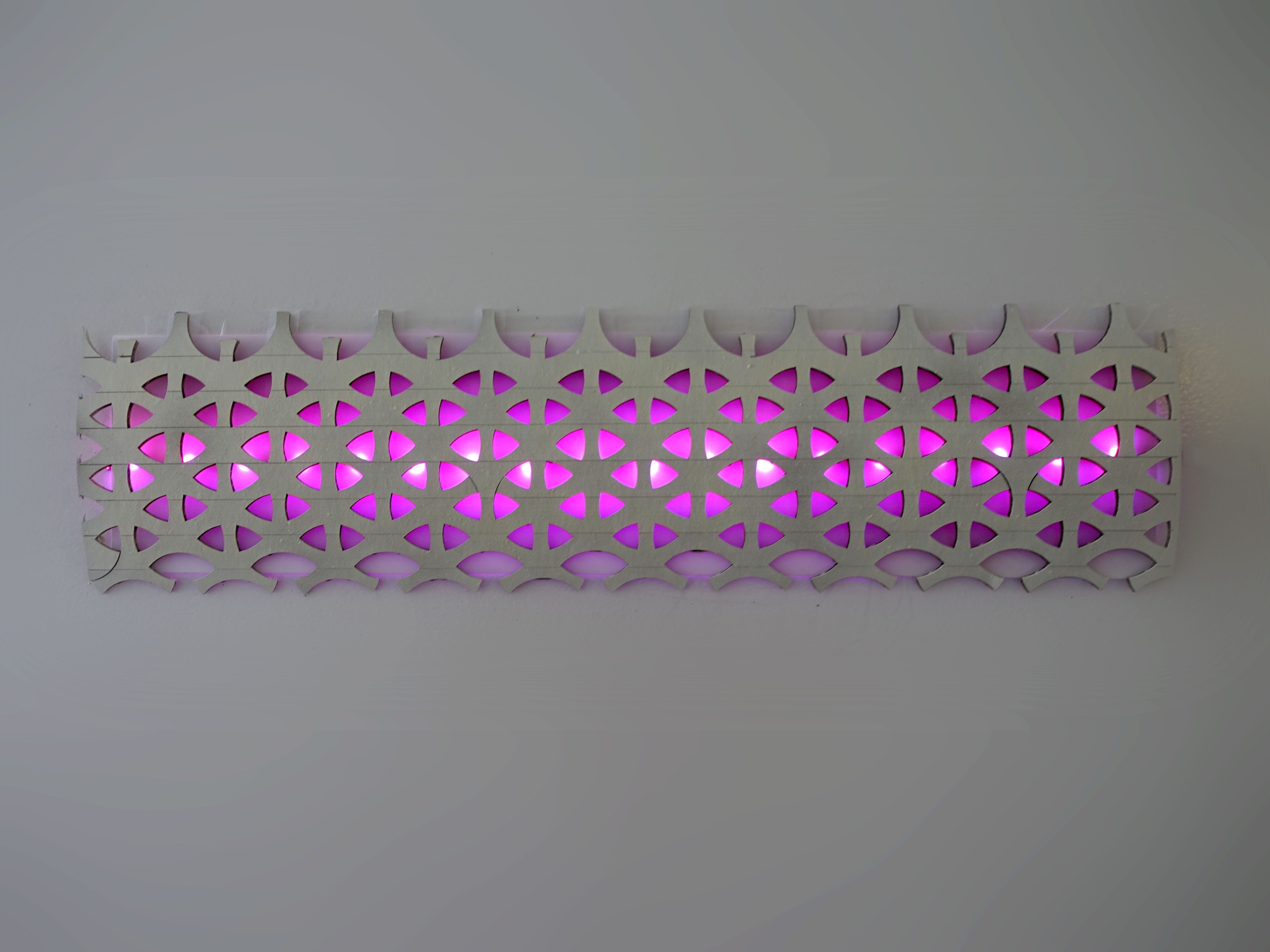
I started making sound reactive LEDs and realized that I can create a wall piece like in Ex Machina. To test this concept, I create a small laser cut card board pattern with a piece of paper as light diffuser. I think it turn out pretty well, except it’s smaller and each LED aren’t individually addressable, I am sure I can redo it with dotStar or NeoPixel to create the same effect as in Ex Machina.
Software: Get sound data
There are 2 parts for this project, sound sensing (Software) and the installation (Hardware).
For sound sending, you can pick up a sound sensor from amazon or other places on the internet, then do an analog read on the sound sensor to map the value to the LED.
For the more advance version, I map the sound in MaxMsp, and apply the lowpass filter and highpass filter to get different colors, then send the signal via serial port via FTDI cable to the Arduino or any Atmega board. The Arduino micro controller then reads the number and map the value to the number.
You can download the MasMsp patch, the Arduino Code, and the pattern for the wall below. Sorry, I did not include the Max application package, it’s too big.
Option 1
I got my 5V LED strip from here. I took it apart using a knife, and de-solder the wires.
For sound sensing, you can pick up a sound sensor from amazon or other place on the internet, then do an analog read on the sound sensor to map the value to the LED.
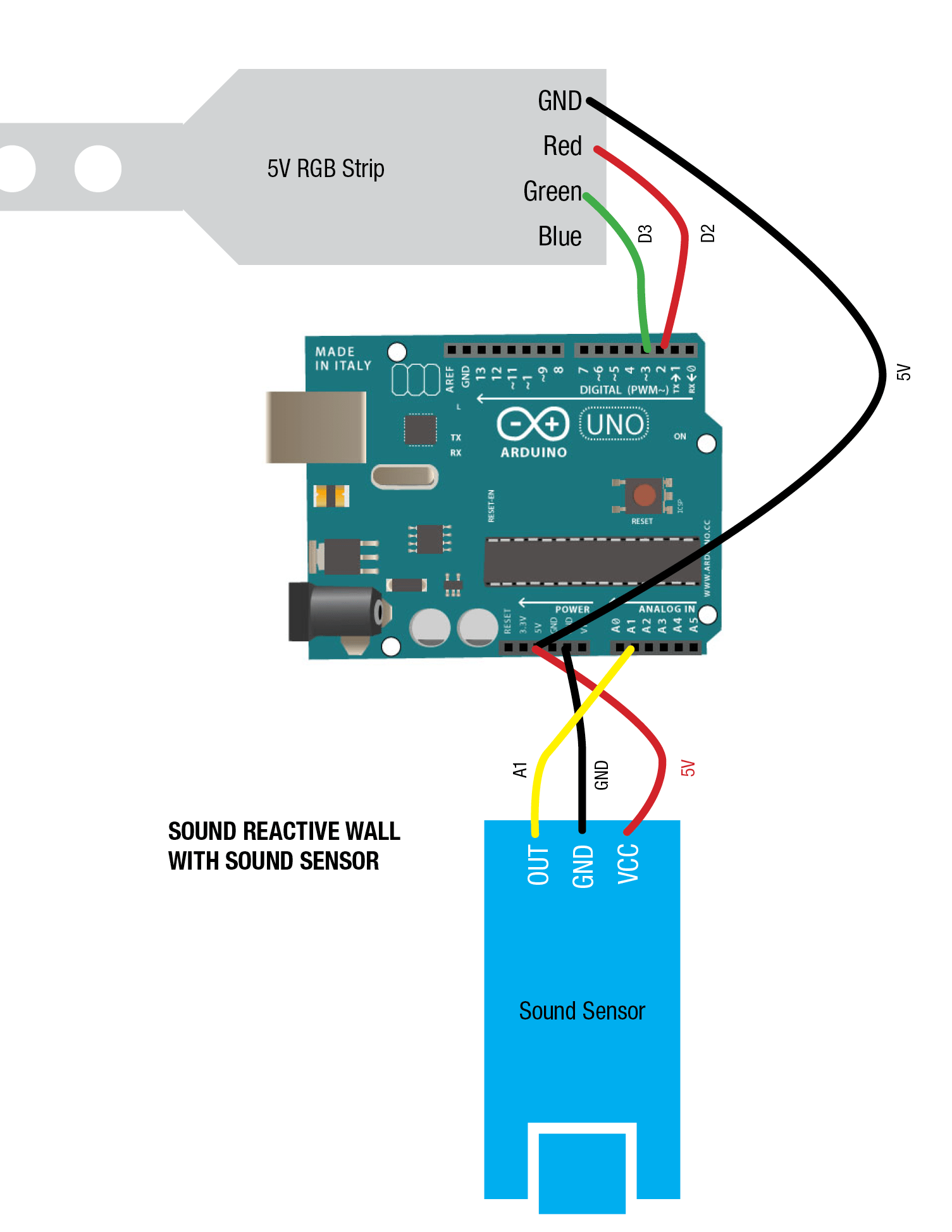
- Black Wire – VCC
- Red Wire -GND -Digital 2
- Blue Wire -GND -Digital 3
- Green Wire -GND – -Digital 4 (optional)
In my code, I only use 3 digital pins to sink current or provide current. It goes like this: Black Wire goes to VCC – 5V logic power Red Wire goes to Digital 2 Blue goes to Digital 3
You can use transistor or MOSFET here if you like to simply the code, but just a little more wiring to do.
Option 2: Get Sound Level with MaxMsp
I got my 5V LED strip from here. I took it apart using a knife, and de-solder the wires.
- Black Wire – VCC
- Red Wire -GND -Digital 2
- Blue Wire -GND -Digital 3
- Green Wire -GND – -Digital 4 (optional)
For the more advance version, I map the sound in MaxMsp, and apply the lowpass filter and highpass filter to get different colors, then send the signal via serial port via FTDI cable to the Arduino or any Atmega board. The Arduino micro controller then reads the number and map the value to the number. If you are using the arduino UNO or LEO, then you don’t need the FTDI cable, they can already talk in Hardware Serial.
You can download the MasMsp patch, the Arduino Code, and the pattern for the wall below. Sorry, I did not include the Max application package, it’s too big.

Hardware Installation: Arduino, LED and Wall piece
First I tried to install the LED strip behind my monitor, that looks interesting and annoying at the same time, so I decided to make the light wall Ex Machina style.

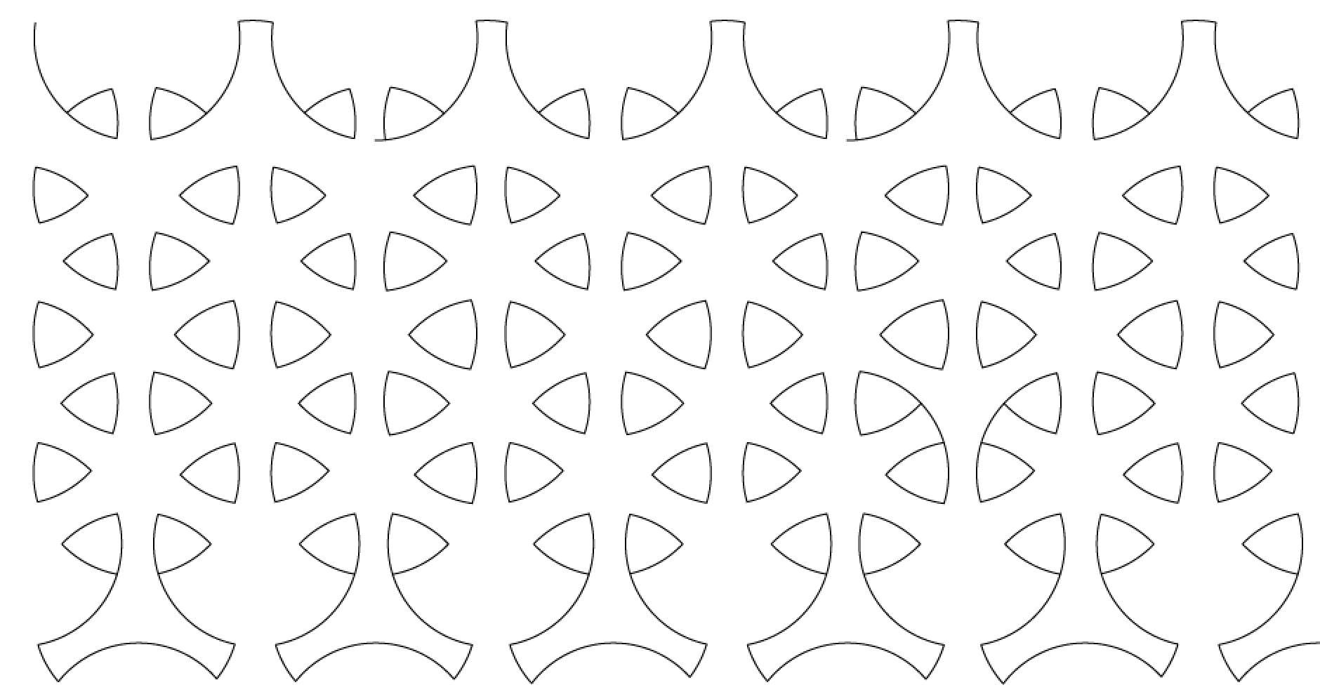
I included the cut file for the wall pattern. I used cardboard in this case, but you can use something stronger
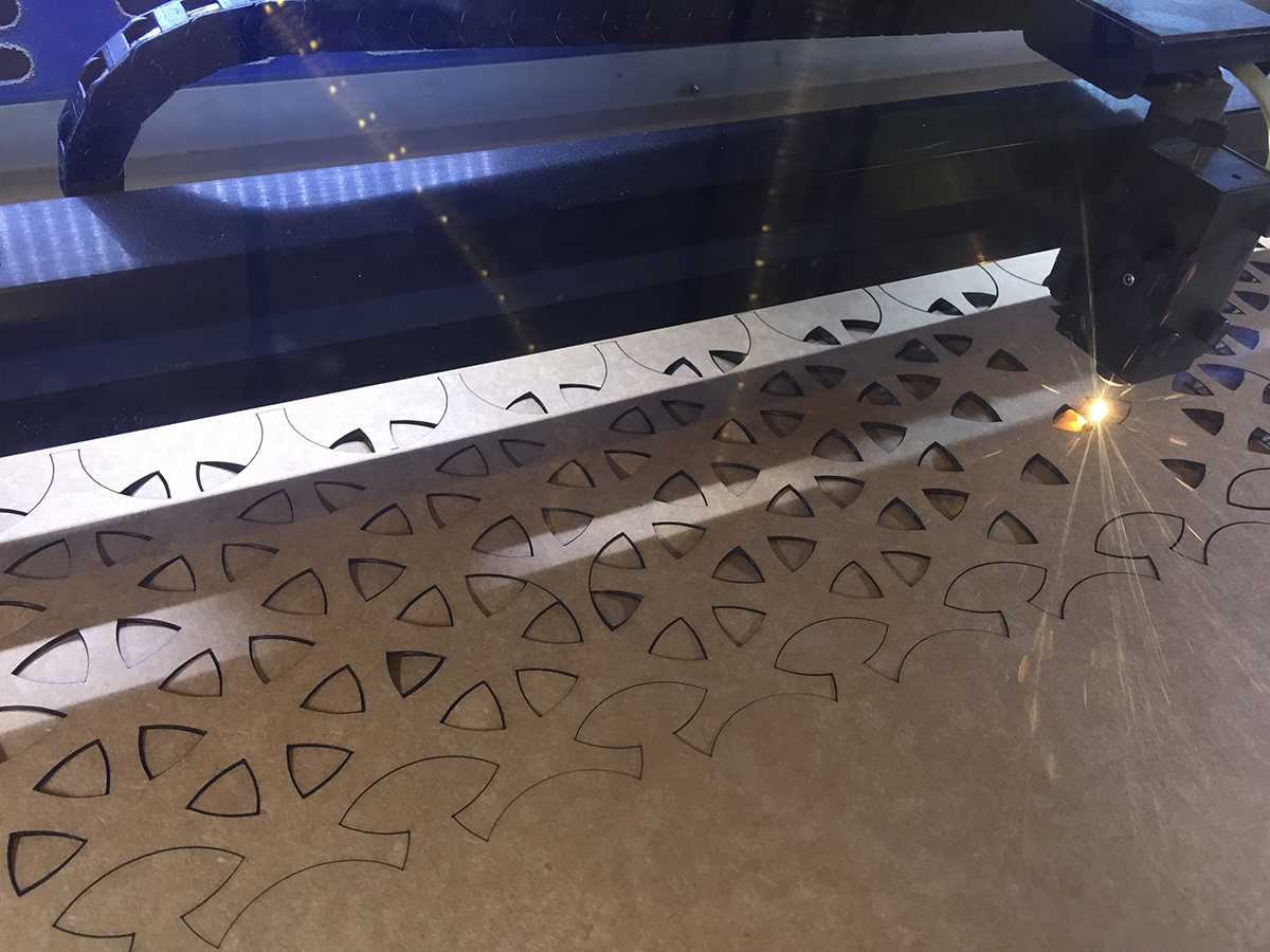
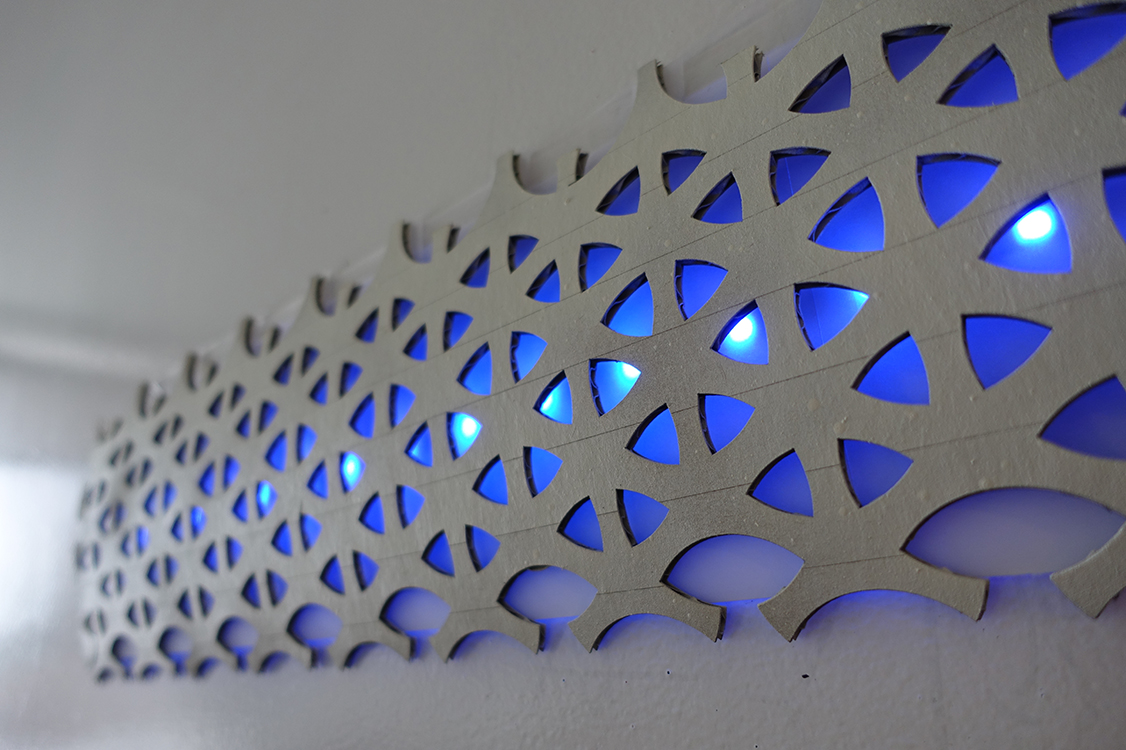
For the wall piece, you need to laser cut the wall pattern, I re-created it in 10 minutes, I am sure you can go back in and make a few more finishing touches. I reproduce the pattern by drawing on top of the overlaying still frame image, but the edges are harder to figure out.
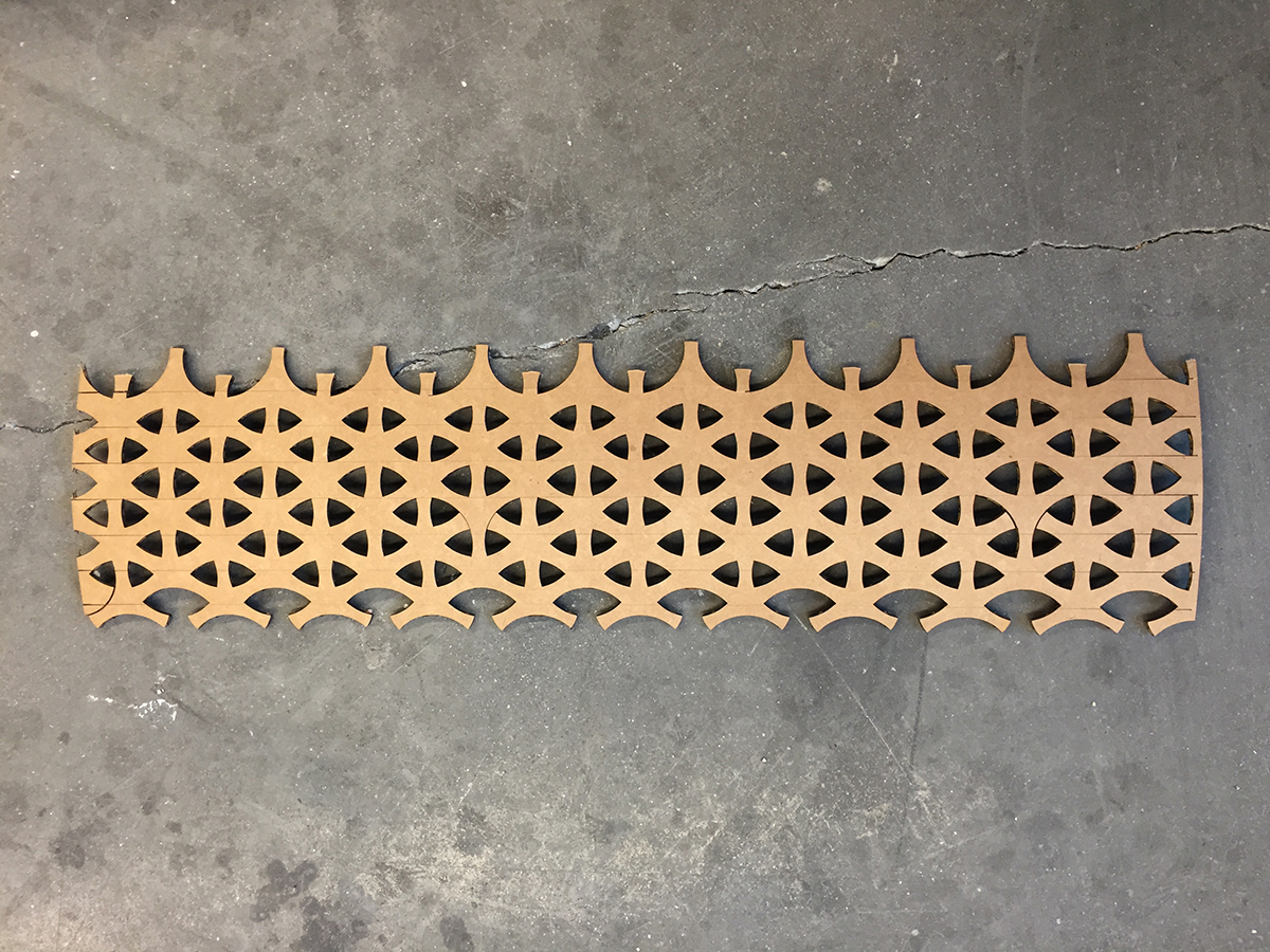
I used laser cutter to cut the cardboard then spread paint it white. I then band it in a slight curve on a cylinder surface to create a small couverture. However you can use white acrylic then use the heat gun to curve the surface.